Engineering & Cost — July 2026
The ±.001 That Didn't Need to Be There
Every tolerance on a print has a price attached to it. Why even overly constrained page tolerances can add significant costs without adding functional value.
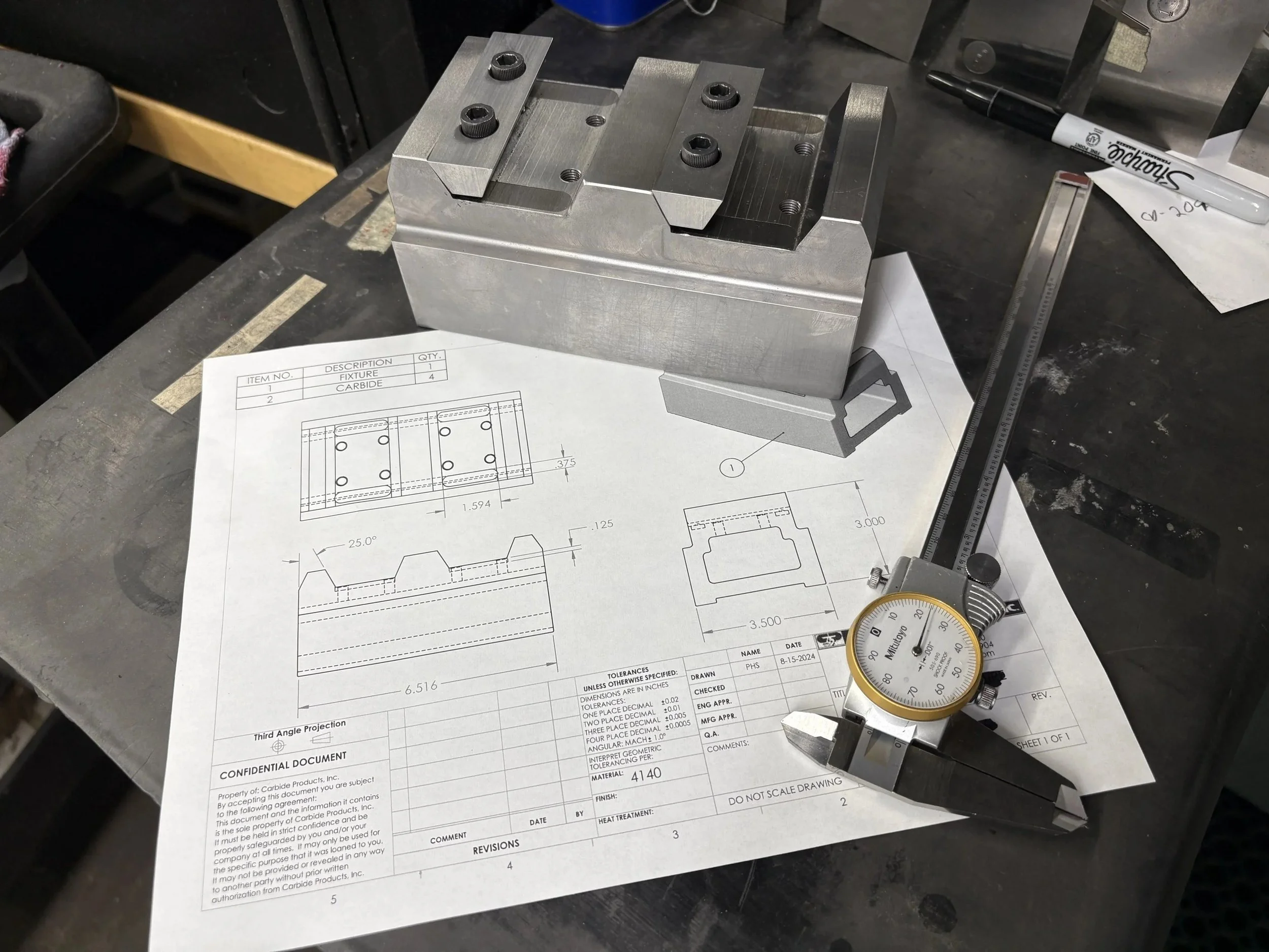
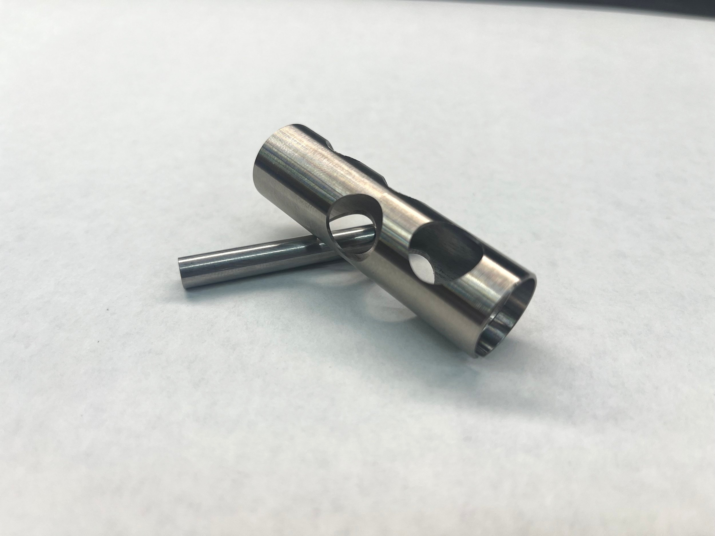
A print came across our floor recently calling out a location tolerance of ±.001" on a feature that, functionally, had no business needing anything tighter than ±.008". Nobody had done anything wrong to get there — the callout had simply been copied forward from an earlier revision, on an earlier part, for a different application, years before. Nobody had gone back to ask whether it still made sense.
That single callout was adding real cycle time, a secondary grinding operation, and a 100% inspection step that a ±.008" tolerance wouldn't have required at all. Multiply that across a running production quantity and it's not a rounding error — it's a meaningful percentage of the part's total cost, attached to a spec that wasn't doing any functional work.
Every Tight Tolerance Has a Price Tag
Tolerance and cost move together, and on a custom part — carbide or otherwise — that relationship is more direct than most buyers expect. A tighter tolerance can mean slower feeds, an added finishing pass, a dedicated fixture, 100% inspection instead of sampling, or a grade change to hold dimensional stability under load. None of that is padding. It's the actual labor and process required to hit the number on the print, reliably, every time.
The problem isn't that tight tolerances exist — plenty of features genuinely need them. The problem is that tolerances rarely get revisited once they're on a print. A callout gets specified once, often conservatively, and then it travels forward through every revision, every reorder, every new supplier, without anyone asking whether the part's actual function still requires it.
Why This Isn't About Cutting Corners
Questioning a tolerance isn't the same as loosening a standard. It's asking a specific engineering question: what does this feature actually do in the assembly, and does holding it to ±.001" change how the part performs, or does it just change how the part is priced? Sometimes the answer is that the tight tolerance is exactly right — in which case, nothing changes and you know the spend is justified. Other times, it isn't, and there's real cost sitting on the table.
Four Questions Worth Asking Before the Next Print Goes Out
These aren't abstract. They're the same questions a good supplier should be asking back at you during print review, before the first piece is ever cut.
01 — Function
What does this feature actually do in the finished assembly?
A mating surface, a wear point, and a reference datum all justify different tolerance levels. If the answer isn't clear, the tolerance was probably set by convention, not by function.
02 — Origin
Where did this specific callout come from?
Was it derived from a stack-up analysis, or copied forward from a prior revision or a similar part? Prints that have been in circulation for years are the most likely place to find a tolerance nobody's re-checked.
03 — Process Impact
What does holding this number actually require on the shop floor?
A ±.0005" callout might mean an added grinding pass and 100% inspection versus sampling. Knowing the process cost of a tolerance makes it possible to weigh it against the part's real requirement.
04 — Documentation
If we change it, is that change traceable?
A tolerance adjustment should go through a formal ECO with sign-off from engineering, not a verbal agreement on a phone call. Good documentation is what makes it safe to question a spec in the first place.
What a Real Print Review Conversation Looks Like
When a print comes to CPI for a first quote, our engineering team reads it the way a machinist has to build it — feature by feature, tolerance by tolerance. If something looks tighter than the application calls for, we'll say so, and we'll explain exactly why: what it costs in cycle time, what inspection step it adds, and what the part would look like without it. The decision to hold the tolerance or relax it always stays with your engineering team. Our job is making sure that decision gets made with the full picture, not left on autopilot from a print that's five revisions old.
That conversation has gone both directions. Sometimes it confirms a tight tolerance is earning its keep — a wear surface that genuinely needs ±.0005" to hit service life, for instance — and the spend is justified. Other times it uncovers a callout nobody's questioned since the part was first designed, and relaxing it by a few thousandths cuts real cost without touching how the part performs.
Either way, you end up with a print that says what it means, priced for what the part actually needs — not for what it's always said.
Get a Quote
Not Sure If Your Tolerances Are Earning Their Keep?
Send us the print. If a callout is adding cost without adding function, we'll tell you — and we'll show our work.
Request a Quote